The following information on homestead water supply and hydraulic ram pump comes from Five Acres and Independence by M. G. Kains. Five Acres and Independence is also available to purchase in print.
So far as family water supply is concerned I may fairly claim to have graduated! At various times I have lived in houses where the primitive rain barrel furnished family needs and reared mosquitoes; where the shallow cistern provoked profanity every winter because holes had to be chopped in the ice and from which the water had to be lifted by a “sweep,” “the old oaken bucket,” or hauled, hand over hand, by rope and pail; a “chain-pump”; where a deep, unprotected cistern was built without provision for drainage and had to be cleaned of noisome sludge, dead toads, mice and other gruesome ingredients every summer; where there was a “filter cistern” which could not be cleaned (!) because of inaccessibility; where an attic tank filled direct from the roof collected leaves, soot, dirt and bird droppings; and where, in several houses, the water had to be pumped by hand either to a tank in the garret or a pressure tank in the cellar. Such experiences prompt me to include a chapter on family water supply and to urge the installation of modern apparatus in every farm home. [*Part of what follows concerning cisterns was published by A. M. Buswell and E. W. Lehman in Circular 393 of the Illinois Experiment Station.]
Rain water is so superior to most well and spring water and is such a money-saver that every farm home should have a supply, if for no other purpose than for the family washing. It requires no “softener,” uses less soap and is pleasanter to work with than even the best water that has come in contact with the ground. Objections to the latter include the brownish or whitish scale that forms in kettles because of its content of lime, magnesia and iron. This scale is a poor conductor of heat thus making necessary the use of excessive fuel. It also clogs “waterbacks” in kitchen stoves and “heating coils” in furnaces, often causes leaks and sometimes explosions.
Lime and magnesia form “curd” or “sludge” with soap and washing powders and spot or stain clothes being washed, and water that contains iron turns brown upon standing, stains pails and makes clothes yellow or stained when laundered. Bleaching such stains shortens the life of the cloth.
To obtain an adequate supply of rain water for household use provision must be made to collect it, to eliminate contaminating materials by screening and filtering, to provide storage and to make the water readily usable. The roofs of buildings are the most common sources of supply, but they are subject to various types of contamination and since water is a good solvent it is quickly polluted. Hence, in collecting a rain-water supply the roof must be thoroughly cleaned by rain before any water is allowed to collect in the cistern. Also the down-spouts always should be disconnected from the cistern by cut-off valves except when water is to be stored. At regular intervals they should be inspected to make sure they are uncontaminated.
Storage may be either above or below ground. Where there is little danger of freezing the former is satisfactory, and where the roof is high the tank may be placed high enough to give pressure without pumping. Such tanks may be of wood, galvanized iron or sheet lead lined and placed inside or close to the house whose roof collects the water.
The commonest storage for rain water is the masonry underground cistern. The walls must be made water-tight to prevent leakage and to avoid the entrance of seepage water. Never should it be located near trees because the roots might crack the walls. Trouble of this kind is most likely to occur with plaster-on-earth masonry.
Cylindrical and rectangular cisterns are both satisfactory. By providing a pipe at the lowest point of the bottom practically all the sediment may be siphoned out when there is a drain to a lower level or pumped out otherwise.
Cistern sizes to serve all practical household purposes depend on three factors: 1, requirements of the family; 2, amount and frequency of rains; 3, area of roof to collect water. The quantity of water depends on the kind of house equipment and the number of persons in the family. When water is pumped by hand less is used than when a gasoline or an electric pump does the work. Five gallons daily per person is a fair estimate where ample hard water under pressure is also available for other purposes. Far more should be provided where there is enough roof area to collect it.
Study of local annual rainfall will help in calculating the size of a cistern when the roof area is adequate. At least 33% of the rainfall should be deducted for leakage, evaporation and to wash the roof. Enough storage capacity should be provided to store water that falls during the rainy period to meet needs during the dry time, better still to have sufficient storage for six months.
Water in a new or a repaired cistern is likely to be hard because of dissolved lime from the plaster or the cement. Thorough curing and setting of the plaster will reduce this difficulty. Curing may be hastened by sponging, spraying or washing the surface of the new plaster or cement with a strong solution of baking soda before allowing the cistern to fill with water, or by filling it with well water and allowing it to stand a few days before emptying it, repeating the treatment if necessary.
Where this condition has not been anticipated and the cistern has been allowed to fill with rain water, the quality of the water may be improved by dissolving one to two pounds of baking soda in a gallon of water, then thoroughly mixing it with the cistern water. It is not advisable to drink water treated in this way because it is highly alkaline, but it may be used for washing.
Even with a cistern carefully constructed and well cared for, it is not always possible to keep the water free from undesirable substances. Soot from coal does not wash easily from roofs so even though the first part of each rain is drained away, the water collected in late fall and early spring is likely to be dark; it gets very dark during winter. This color may be removed by adding carefully prepared solutions of alum and soda to the water to form a sludge which when it settles will carry the color with it. Wrong proportions will give poor results. Make two solutions as follows:
1. Dissolve 3/4 pound of baking soda in 1 gallon of water. 2. Dissolve 1 pound of alum (potassium aluminum sulphate crystals) in 1/2 gallon of water. (“Filter alum”—aluminum sulphate—is cheaper than alum and may be used if available. Use 1/2 pound to 1/2 gallon of water. Do not used “burnt alum.”)
Determine the amount of water in the cistern by multiplying the area by the actual depth of water (1 cubic foot contains 7 1/2 gallons). For each 30 gallons of water add 1/2 pint of solution No. 1 and stir. Next add 1/4 pint of solution No. 2 for each 30 gallons and stir again. Allow 24 hours for the precipitate to settle to the bottom, after which the water above the sludge will be clear.
The relatively small amount of sediment precipitated will not cause inconvenience. Mud and dirt that always accumulate in a cistern should be removed, together with the precipitate, once each year when the supply of water is lowest.
In spite of precautions leaves, mice, toads or insects sometimes get into cisterns and produce bad odors. The proper thing then is to clean the cistern thoroughly. In dry years, when this waste of water may be serious the water may be deodorized and made satisfactory for all uses except drinking, by treatment with chloride of lime which burns up the odor. Mix about a tablespoonful in a porcelain, glass or crockery dish with two or three tablespoonfuls of water; rub the lumps with the spoon, then add about a quart of water. Stir thoroughly and pour the solution into the tank, mixing it intimately with the cistern water by stirring with a long board or a paddle. If this treatment is not adequate, use a second or a third dose if necessary. This chemical is harmless unless used in excessive amounts.
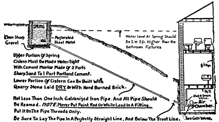
A spring may often be the source of a water supply. When higher than the point of use pipes placed below the frost line may be laid so the water will flow by gravity. Though the system usually works well, trouble is sometimes met by the gradual reduction and finally stoppage of the flow. Generally this is because air has collected, little by little from bubbles in the water and lodged in some irregularity of the pipe. The less the grade, the smaller the pipe and the slower the flow the greater the likelihood of such trouble because the bubbles will not be carried down by the current but gradually work back to a high spot.
To avoid difficulty the pipe should not be smaller than 1″. Standpipes may be tapped in at high spots to allow the air to escape. The entrance to the pipe should be 6″ or more above the bottom of the spring well and be protected by a screen to prevent anything but water getting in. The pipe itself should be laid as straight as possible, with neither dips, rises, nor avoidable angles. All joints should be well leaded and screwed tight so as to cover all the threaded parts.
That this kind of system works well where conditions are favorable I can fully attest because one place owned by a cousin and another rented by my father when I was a boy were supplied by springs considerably higher than the house. The water was conveyed in “pump-logs” and in the latter case the pressure was great enough to throw a stream over the house. It had its source more than half a mile distant.
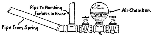
The pressure or pneumatic water system is doubtless most popular of all used in farm homes because it is efficient, simple to install, easy to operate, reasonable in cost and adaptable to a wide range of conditions. The one I installed on my farm to supply both house and barn (150 feet away) was pumped by hand until an electric company supplied current. (Fig. 10.)
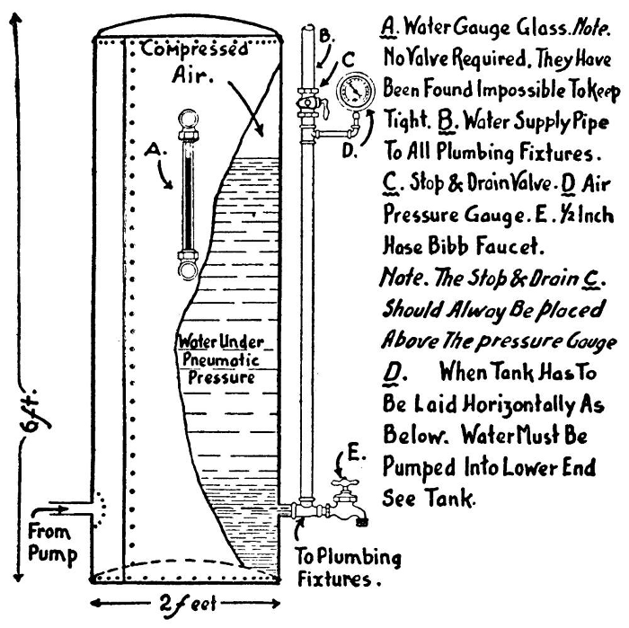
As water is pumped into one of these closed tanks the air is condensed to a fraction of its original volume, so its pressure is increased. When thus half filled with water the pressure is about 14 pounds to the square inch above the pressure of the open air and will so be indicated on the pressure gauge attached to the tank. When the tank is two-thirds its capacity full the gauge pressure will read about 28 pounds and at three-fourths capacity about 42 pounds, the usual maximum pressure for ordinary service.
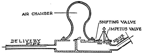
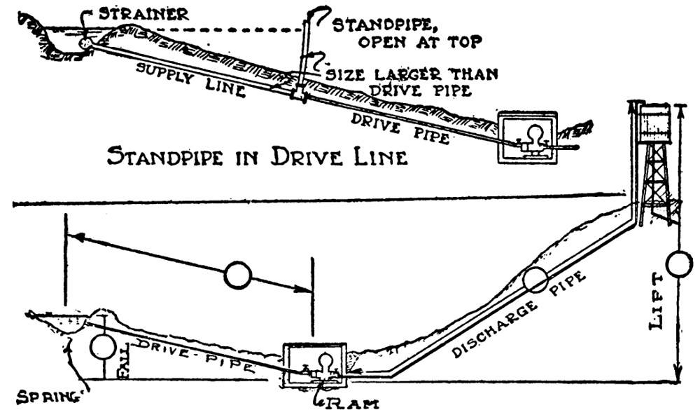
Where conditions are favorable the hydraulic ram pump* or the hydraulic “engine” is usually the most satisfactory and least costly apparatus to install and operate for pumping water. (Fig. 11) The machine is a device by which the momentum of a column of water flowing in a pipe forces a small part of itself to a higher level than its source. It may be used wherever water in sufficient volume can be piped from its source to a lower level of several feet. Some styles are built to use impure water for operation but pure water for delivery. [*Much of what follows is condensed from the Kentucky Experiment Station Bulletins.]
Water flows through the drive pipe to the ram pump and out through an impetus valve. It gains velocity until its momentum closes the valve, whose sudden closing forces the moving column of water to open a valve in the bottom of an air chamber, drive water in and compress the air until the water column has spent its energy. Then the air-chamber valve closes and the compressed air forces water through the delivery pipe to the reservoir. When the air-chamber valve closes the water column in the drive pipe rebounds slightly, removes pressure from the impetus valve which then opens and re-starts the cycle. This repetition continues as long as the drive pipe is full of water. In order to work the following conditions must be met:
The fall from the supply to the hydraulic ram pump must be at least 2′ and the minimum flow 1 gallon a minute; but the fall necessary depends on the volume of water needed and the height it is to be pumped.
The fall may be measured with a carpenter’s or a surveyor’s level or with a garden hose used as a siphon from the source to the point where the ram pump is to be located. In the last case the hose must be lifted at its lower end until the water no longer runs out but stands at the opening which is pointed upward. The distance from this point to the ground is the height of the fall.
The lift or height to which the water is to be raised should not be more than 10 or 12 times that of the fall. This height is the vertical distance between the level of the ram pump and the top of the reservoir.
According to the ratio of the fall to the lift a ram pump discharges approximately 4% to 15% of the water supplied to it. The approximate quantity discharged a minute equals the product of the fall in feet by the number of gallons a minute supplied to the ram pump, divided by twice the lift.
When writing manufacturers concerning the size of ram pump needed, cost and method of installation, be sure to include the following information:
1. Flow of spring, or number of gallons a minute the spring supplies. 2. Fall or vertical distance from the water level in the supply basin to the location of the ram pump. 3. Distance from the source of water to the ram pump location. 4. Length of pipe needed to deliver the water from the ram pump to the storage tank. 5. Lift, or vertical height above the level of the ram to the level of discharge at the reservoir. 6. Maximum number of gallons of water needed daily to meet all demands.
Should a ram pump work imperfectly or stop any one of several causes may be responsible. If the flow is insufficient in the drive pipe, close the gate valve on that pipe at the ram pump until enough water has accumulated; then open it and start the ram pump by pressing down the impetus valve, allowing the water to escape, then permitting the valve to rise again. After several such repetitions the ram pump should operate automatically. By shortening the stroke of the impetus valve the ram pump may be made to use less water. This may be done with a simple adjustment. Sand or twigs or leaves sometimes get into and clog the impetus valve. Thorough flushing and cleaning both valve seats is indicated. When the valves become worn they must be replaced. Usually they last for several to many years if the water is free from sand or soil.
Perhaps the commonest cause of stopping is insufficient air in the air-chamber. Pressure in this compartment makes the water absorb air, so unless new supplies are taken in the apparatus will stop. Ram pumps generally have snifting valves to take in air with each stroke but sometimes these become clogged. They are easily cleaned with a small wire. With each stroke they suck in a little air which rises in the air-chamber and thus maintains pressure.
Click here to purchase Five Acres and Independence in paperback
