The following information on the Belgian Mauser Model comes from Chapter 14 of Mauser Rifles and Pistols by W. H. B. Smith. Mauser Rifles and Pistols is also available to purchase in print.
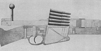
In response to the request of the Belgian Government for the submission of test rifles, weapons were supplied by manufacturers from many countries. After extensive and detailed testing, the Belgian Government finally accepted the new Mauser rifle. This was the first weapon manufactured by Mauser to employ a box magazine, and the first on which his now famous cartridge clip was used as a quick loading instrument. With only minor modifications, this rifle was officially in use by the Belgian Government in World War I. The essential design of the rifle was so correct that only minor modifications were necessary; and even the most modern Mausers vary from it in detail rather than principle.

Specifications
The caliber of this model is 7.65mm or .301 inch. The overall length is about 50 inches. The barrel measures 30.7 inches. The rifle weighs about 8.5 pounds without bayonet, the bayonet adding an additional pound.
The arm may be loaded with individual cartridges or may be loaded with 5-rounds directly from the clip. No cut off is provided, but the magazine may be charged at any time by opening the action and inserting cartridges. The rifling is 4-grooves to the right with a twist of 1 in 9.842 inches. The sights are rear notch and front barleycorn. The range of sight graduation is from 500 to 2000 meters. No wind gauge is provided. This rifle is noteworthy also for the introduction of the one-piece bolt with full-forward locking lugs, the strongest system known. The overall length of the rimless cartridge according to Loewe is 3.07 inch, while the length of the rounded-nose cupro-nickel bullet is 1.2 inch. The loaded cartridge weighs about 441 grains. The bullet with a nickel jacket weighs about 229 grains. The original powder charge was 47.4 grains of smokeless but this charge varies in later loadings as powder efficiencies increase. The average standard today is about 42.5 grains to give the same ballistics as the original load.
The muzzle velocity is about 2034 feet per second with a chamber pressure of about 39,400 pounds per square inch. Bullet diameter is .31 inch maximum. (Note: Current loadings for this cartridge, as well as bullet styles, vary with time and place of manufacture).

Barrel Characteristics
The barrel of the Belgian Mauser differs from that of most of the others in that externally it is left rough from the turning tool. The barrel is quite thin and its diameter at the breech end is about one-inch greater in front of the chamber and again about the center of the chamber. It is screwed into the receiver in standard fashion.
The particular characteristic of the Belgian Mauser is the thin tube of solid drawn steel which covers the barrel and is intended to protect it and also to protect the hands of the riflemen by diffusing the heat when using the weapon in rapid fire. A ring shrunk about the muzzle end of this tube carries the block for the front sight and the cleaning rod holder. A collar at the front end of this ring provides a mounting for the cross-bar of the sword type bayonet.

A somewhat thicker cylinder is fastened by the screws at one end to the rear of this casing and at the other to the receiver. A pin extends downward from this into a bushed hole in the stock. The rear sight is brazed onto the casing just ahead of the front reinforce. The sight resembles that of the Lee-Enfield rifle except that the V-notches in the slide and the cap are smaller.
A groove is cut on either side of the boltway to permit the working of the bolt lugs and the extractor. The right side groove is partly cut away to permit ejection of cartridges to the right. The recesses for the locking lugs on the bolt are at the front end of these grooves.
The rear part of the receiver forms a complete cylinder in which the bolt moves; while beyond this cylindrical point it is prolonged into a tang provided with a groove for the cocking stud.
The receiver is further cut out below to receive the magazine, and there is a cut in the tang to receive the tooth of the sear where it projects into the groove for the cocking stud.

Bolt Design
The bolt itself is exceptionally strong and of very simple construction. It is made in one piece, hence the bolt head is not removable as in early models and in most Mannlicher designs. No tools are needed to dismount it. The locking lugs at the front end of the bolt are placed opposite one another, providing a breech lock directly and firmly behind the head of the cartridge case. This is the most substantial form of breech locking ever devised. All later important military rifles with the sole exception of the British utilize this form of locking. The British “Pattern 1914” used Mauser-type locking, but all the earlier Lee-Enfields and the new Marks of British service rifles retain the old Lee rear lug system.
The face of the bolt is recessed to receive the base of the rimless cartridge. The bolt handle projects at right angles from the rear of the right side of the bolt and ends in a round knob.
A cam-shaped recess at the back end of the bolt serves to partly cock the striker when the bolt handle is turned up; a thrusting movement being imparted to the cocking-piece and striker which cannot turn, as they are acted upon by the turning bolt cylinder. On the opposite side there is a small notch for the tooth of the safety bolt.
The mainspring if of coiled wire, usually 28 coils, measuring .06 inch in thickness.
The striker is provided with a short point and a collar against which the mainspring bears for cocking. The end of the striker is threaded to receive the cocking-piece.
On the under side of this cocking-piece is a projection traveling in a groove cut for it in the tang of the body. This projection engages with the sear nose when the rifle is at full cock. Its front top surface is beveled off to work in a cam slot in the rear of the bolt.
The bolt plug screws loosely into the rear end of the bolt with the mainspring bearing against the front end. The cocking stud working in a slot prevents the bolt plug (or cocking-piece) from revolving with the bolt when the bolt lever is raised.
A rib on the striker prevents the striker from turning in the bolt plug. There is a cylindrical hole in the top of the bolt plug to receive the stem of the safety bolt. The front of the stud on the cocking-piece rests in a small groove at the rear of the bolt and prevents the bolt plug from turning should the safety bolt not be holding back the cocking-piece.
The safety bolt itself is a thumb-piece and a spindle working in the hole in the bolt plug. When the rifle action is closed, and the thumb-piece turned vertical, the flange on the safety bolt is pushed up in front of the top of the cocking-piece to force it back a short distance and enable it to withdraw the stud from contact with the sear. When the thumb-piece is turned to the right, the cocking-piece is still locked, but the end of the stem where it is not cut away enters into the slot at the end of the bolt, locking the bolt and plug together to prevent the bolt from being revolved.
This safety bolt is retained in position by a small pin actuated by a spiral spring which works in a groove cut across the top of the bolt plug. The spring and pin are retained in position by a screw.

Extraction System
The extractor is a short spring terminating in a claw. It is mounted into the right side of the bolt in position between the two locking lugs and as the bolt revolves the extractor turns with it. This differs from the other designs of the same manufacturer.
The bolt stop is in the form of a hinged lever with a tooth projecting into a groove in the receiver for the left locking lug of the bolt. This lever is pivoted and is kept pressed against the receiver normally by a flat spring which is led into it. When it is pulled away from the receiver by drawing on its flap, it pivots and permits the bolt to be withdrawn from the rifle. (In this model a flap formed to slide against the side of the receiver replaces the rib found in most Mausers).
The ejector is a flat piece inside the retaining bolt. It works on the same pivot pin and is actuated by the spring inside the lever. It projects into the boltway. A slot is cut for it in the left locking lug and in the face of the bolt itself. Thus when the bolt is drawn back, the ejector springs into this slot so that the base of the cartridge strikes against it. As the extractor continues to pull back the right side of the cartridge, this combined motion swings the cartridge case around and throws it out of the action to the right.
The sear projects into the groove cut into the tang of the receiver and is part of a bar pivoted at its front end to the receiver. It is operated by a spiral spring led into it whose other end bears against the receiver. The spring in this type is horizontally placed.
The trigger is pivoted to the bar portion of the sear in which there is a vertical slot. No half cock is provided. The striker cannot be placed at full cock except by opening and closing the action. The pull off is double in standard military practice. The first pull is a sliding movement. This permits the slack to be taken up ready for the actual releasing pull. When this first movement is completed, the leverage shifts. On continued pressure the trigger and sear move to free the seal from the striker bent. The striker is then driven forward by its compressed spring.

Magazine Construction
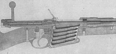
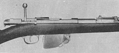
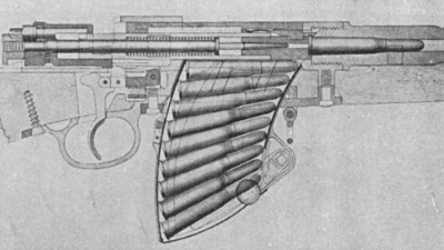
The magazine holds 5-rimless cartridges in a single column. It is a short steel box whose bottom is hinged to the sides at the rear end fastened by a screw at the front end. This screw acts as a pivot for a flat lever actuated by a flat spring attached to the bottom of the magazine. A second flat lever is hinged to the end of the first one and forms the follower for the cartridge (the platform on which the cartridge rests). A second flat spring attached to the lower lever raises the upper one.
The magazine sides are turned in at the top almost their full length to hold the cartridges in the box. Horizontal and vertical cuts in them permit the sides to act as springs of sufficient elasticity to spread when the cartridges are forced down in the magazine, yet are sufficiently strong to hold the cartridges from being pushed out by the rising follower. The magazine passes up through an opening in the prolongation of the trigger guard where it is held in position by a small lever catch pivoted to the guard and operated by a small spiral spring. This magazine projects below the bottom of the stock.
This Belgian pattern is not provided with the customary rib on the magazine platform to serve as a bolt stop when the last cartridge has been fired.
The stock is one piece. The stock, receiver and trigger guard are fastened together by screws. The stock is screwed into a boss extending at right angles to the axis of the barrel which serves to pass on the recoil of the barrel and receiver to the stock, thereby saving the screws from being broken by the shock.
A projection beneath the upper band is provided to attach the short bayonet. A full length cleaning rod screws into a nut in the stock. Its head has a slot in it which fits into the rod holder of the front sight ring.
The butt plate is steel and is fastened with two screws. Normally it is not provided with a trap.
