The following information on the Mauser-Norris 67-69 Continued comes from Chapter 3 of Mauser Rifles and Pistols by W. H. B. Smith. Mauser Rifles and Pistols is also available to purchase in print.
In the interests of historical documentation, the following literal translation from the German of the description given by Theodor Schmid, Director of the Waffenfabrik Mauser A.-G. at the turn of the century, is of distinct value.
Schmid was a personal friend and confidant of Paul Mauser, and his description of the earliest Mauser rifles, as well as his sidelights on Norris, had the approval of the great inventor.
These details, therefore, constitute the best available authority on one phase of Mauser’s activities and weapons which has long been the subject of conjecture and misinformation. (Note: Schmid uses the term “chamber” in reference to the long cylindrical bolt body. The term “shoe” means the receiver.
Single-Loader With Cylinder Lock, Mauser-Norris C. 67/69

History: The single-loader described below was created in the years 1867-1869, with the financial support of the American Samuel Norris, whose assistance enabled the brothers Paul and Wilhelm Mauser to work out in Lüttich the novel ideas, conceived especially by Paul Mauser, relating to the improvement of the then still very imperfect breech-loading system with a cylinder lock, with particular consideration to the use of metallic cartridges. The efforts of the two brothers were crowned by success; the experimental weapons then produced in Lüttich (see the pictures which follow for a complete representation of these rifles) embody already all the essential improvements which carried the later Mauser rifles, first as single-loaders, to triumph and glory all over the world.
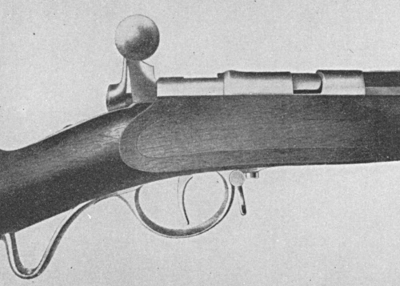
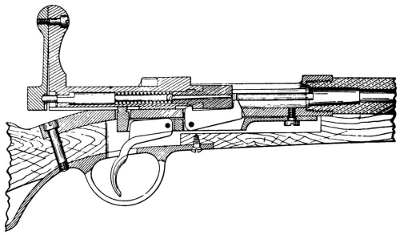
Principle: As the picture shows, this first complete Mauser-Norris rifle already displays the following arrangements, so important in principle:
1) The lock is designed for self-cocking.
2) The cylindrical block, the so-called “chamber,” bears on its forward end a rotatory bolt-head which, due to its rotatory connection with the chamber is not affected by the rotation of the latter, so that when the chamber is opened or closed, this bolt-head retains its position, i.e. does not turn.
(This arrangement resulted in a better obturation of the then still used paper cartridges in particular, inasmuch as due to the nonturning of the bolt-head during the closing, the bottom of the cartridge was not exposed to friction, and therefore remained undamaged. From the point of view of the planned introduction of metallic cartridges, however, the rotatory bolt-head represented the great advantage of permitting the use of an extractor fastened immovably to the bolt-head.)
3) During opening, the fired empty cartridge is pulled back by a curve on the breech-shoe.
4) During opening, the striker is pulled back so far as to make its tip move behind the front surface of the breech face of the chamber, respectively of the bolt-head, thus preventing the possibility of a premature ignition due to the projection of the tip of the striker during loading (forward drive of the cartridge into the barrel).
5) The arrangement includes the extractor, fastened stationarily to the bolt-head (as mentioned under 2), which is especially valuable when metallic cartridges are used.
6) A special ejector is provided, which, too, is of great importance for the use of metallic cartridges.
1st Model: The following are the details of the mechanism of the Mauser-Norris rifle designed along the general principles outlined above:
The breech shoe is perforated, and on its rear face, behind the perforation on the left-hand part of the shoe, there is a curve, along the surface of which the handle is driven a little backward when the cylinder (chamber) is turned up, thereby forcibly dislodging the fired cartridge from its position.
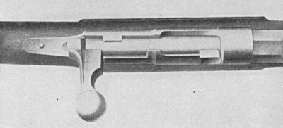
The bolt-head is seated on the forward end of the chamber, and is protected by a combination of projections and recesses against longitudinal dislodgements.
In order to produce a double-side locking device there is a comparatively big stud on the chamber, below the forward end, in the same plane with the handle; a matching counter-stud is provided on the opposite side, but this counter-stud is located slightly farther forward, and is completed by a stud located on the bolt-head and extending in the same direction.
The formerly used thin firing needle has been replaced by a strong striker. The mainspring, fashioned as a leaf-spring, is attached to the handle above, and forms one piece with the snap, the lower end of the spring being fashioned so as to form a cup to receive the striker. A spiral spring is pushed onto the forward part of the striker; this spring tends to keep its rear end pressed into the cavity of the cup-shaped snap, so that when the snap is moved backward during the cocking of the mainspring, also the striker will follow this backward movement.
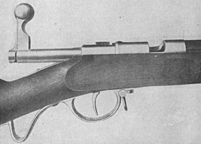
During closing, the self-cocking of the lock is effected as follows: The rear end of the chamber has a recess, into which the upward-pointing sear snaps when the chamber is moving forward. Thus the sear stops in front of the snap, the inside face of which has a curve-shaped chamfering. When the cylindrical block is turned closed, this curved chamfering slides on the cocking stop, whereby the snap is forced back, and the mainspring is cocked.
During opening, the striker is pulled back as follows: Matching shoulders or chamferings are provided on the forward part of the striker and on the rear end of the stock of the bolt-head, and when the chamber is turned up, their concerted action impart a slight backward movement to the striker. The striker can occupy the position of ignition only when the locking is completed, i.e. the chamber is turned closed, when the shoulders and chamferings face each other in such a manner as to leave the striker free play to protrude sufficiently over the frontal face of the bolt-head.
The trigger mechanism shows a trigger rod with the sear, which latter also serves as cocking stop. The sear is attached to the rear end of the rod in such a manner that when the trigger is pressed, it is forced down, so that it is separated from the snap, whereby the action of the mainspring causes the snap to fly forward, carrying along the striker which lies in its cavity.
The extractor is attached laterally to the bolt-head; a special groove is provided for it in the inside wall of the breech shoe, which serves as its guide-way when the chamber is opened and dosed. When the chamber is moving back and forth, the extractor slides in this groove, whereby also a rotation of the bolt-head is prevented during the turning of the chamber up and down.
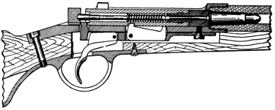
The extractor is lodged in the bottom of the lock shoe, in such a manner as to permit it to swing. In the chamber there is a recess to receive the rear end of the extractor (bent as a hook in front) when the locking is effected, so that the extractor is kept motionless. When the chamber is pulled back, the rear end of the extractor slides out of the recess, so that it is swung into its action position with its hook or ejection shoulder upward, thus giving the extracted empty cartridge case the necessary impetus for the ejection.
Patents: Of all the patents taken out for the innovations described above, United States Patent No. 78603 is of the greatest interest to us right now, for this single patent, awarded in the name of Norris and the Mauser brothers, is actually a summary of all the innovations covered by the various individual patents issued in other countries. We reproduce here literally its introduction and claims, as well as the drawings which form part and parcel of it. As regards the patents awarded in other countries, not requiring an identification of the inventor, we quote here abstracts from Austrian Patents 17864 XIX9 and XIX26 which are in German, and will therefore be clear to the reader. These patents, representing the fruit of the work of the Mauser brothers (in particular of the practical labor of Paul Mauser), show beyond the shadow of a doubt that the weapon covered by these patents, and which became known to the general public as the “Mauser-Norris rifle,” or simply as the “Norris rifle,” actually embodies the principal technical features of the Mauser lock, wherefore it is of utmost importance not only from the historical point of view, but also practically in the development of Mauser rifles, and of portable firearms in general.
2nd Model: Some time after the completion of the weapon known as “Mauser-Norris rifle,” another model rifle was perfected; as regards its lock arrangement, this later model is identical with the single-loader described above, but it embodies certain detail improvements, and it represents in fact the intermediate stage between the “Mauser-Norris rifle” and the German M.71 rifle. As far as it can still be ascertained, this rifle shows the following changes:
The mainspring (attached to the handle in the previous model) is dispensed with, and replaced by the strong spiral spring, lodged in the chamber and surrounding the striker.
A guide-rib is provided for the chamber; this guide-rib is joined to the foot of the handle, and it forms the breech base. Its forward part, protruding over the end of the chamber, has a transverse groove or notch, and when the breech mechanism is opened, this groove or notch extends with a shoulder over a nose of the bolt-head (which is inserted into the chamber end without any coupling, i.e. without any stop to prevent its longitudinal displacement, although it does not share the turning movement of the chamber), carrying the bolt-head along when the chamber is pulled back.
The snap is pushed on the rear end of the striker, as a separate part, and is kept in its place by the separate striker nut, screwed onto the striker behind the snap.
The self-cocking is effected as follows: A projection is provided on the forward end of the snap, and a chamfering or recess on the rear end of the chamber, so that they engage each other when the locking is effected. When the chamber is turned up, the projection and the recess slide along each other, whereby the snap is forced back, and the spiral spring, surrounding the striker and serving as mainspring, is cocked.
Furthermore, this rifle was the first to have a safety device of the cocked lock, in connection with the snap; this safety device consists of an adjustable retaining piece which takes up a position between the chamber and the snap when the handle is pointing upward, thus preventing the snap from flying forward.
Patents: The financial backer who had applied for a patent for the first “Mauser-Norris design” for his own account and in his own name, neglected to have the above improvements patented. The Mauser brothers were not in the position to apply for the necessary patents, for at that time whatever modest financial resources they possessed were needed primarily for the expenses of the production of the various test and trial rifles. Moreover, it was anyway impossible to acquire a sufficiently ample patent protection in the German States, for it is a well known historical fact that in the absence of a universal German Reich patent law, there was no patent protection available in those days for the entire territory of the Reich.
