The following information on the Mauser-Norris 67-69 comes from Chapter 2 of Mauser Rifles and Pistols by W. H. B. Smith. Mauser Rifles and Pistols is also available to purchase in print.
This single-loader was developed during the years 1867-1869 by the brothers Paul and Wilhelm Mauser, with the financial support of an American, Samuel Norris.
At this period Lüttich was the fountainhead of European arms development, and it was there the actual manufacture was done.
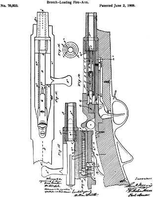
No better description of this arm can be given—and certainly none more historically accurate—than that found in the records of the United States Patent Office, where this first successful Mauser rifle was originally patented:
AUS DEM AMERIKANISCHEN PATENT 78603 VOM. 2.
JUNI 1868
(Originalabdruck der Einleitung und Zeichnungen)
Ferner patentiert in Frankreich, Belgien, England and diversen anderen Staaten
UNITED STATES PATENT OFFICE
Samuel Norris, of Springfield, Massachusetts, and Wilhelm Mauser and Paul Mauser, of Oberndorf, Wurtemburg, Assignors to Samuel Norris.
Letters Patent No. 78,603, dated June 2, 1868.
Improvement in Breech-Loading Fire-Arms.
The Schedule referred to in these Letters Patent and making part of the same.
TO ALL WHOM IT MAY CONCERN.
Be it known that we, Samuel Norris, of Springfield, Massachusetts, United States of America, at present residing in London, England, and Wilhelm Mauser and Paul Mauser, both of Oberndorf on the Neckar, in the Kingdom of Wurtemburg, have invented certain new and useful “Improvements in Breech-Loading Fire-Arms”; and we do hereby declare that the following is a full and exact description thereof, reference being had to the accompanying drawings forming a part of this specification.
The said improvements relate, first, to breech-loading mechanism of novel construction for fire-arms, whose breech is closed by a cylindrical block fitted to slide endwise in a chamber at the rear of the barrel. The said block is provided with a catch or projection extending from its surface, and, to close the breech, is turned upon its axis, so as to bring the said catch in front of a shoulder on the side of the breech-chamber, and thereby keep the said block securely up to the breech. In opening the breech, the catch is turned back into line with a longitudinal aperture, which allows the said catch to pass, and the block to be drawn back.
The cartridges are ignited by the blow of a firing-pin, which passes through the cylindrical block, and is driven forward by a spring, which is held by a catch, and is released by means of an ordinary trigger.
The said improvements consist chiefly in the peculiar construction and arrangement of the main-spring, and in the devices employed in connection with the trigger for holding and releasing the said spring. The latter is attached at one end to the extremity of a handle, which projects radially from the rear of the cylindrical breech-block, the other end of the said spring being free, and arranged exactly opposite the centre of the said block, which is in line with the barrel.
The rear end of the firing-pin lies in contact with a head formed on the end of the spring, and when the latter is released from its catch, it drives the said pin forward into contact with the cartridge in the charge-chamber. The said pin is kept in contact with the head of the main-spring by a light spiral spring, which bears against the rear end of the pin, and the forward end of the breech-block.
The head of the main-spring lies close to the end of the cylindrical block, except when the piece is cocked, and is formed with an inclined surface or cam. This surface is arranged to act in such a manner upon the catch or stop that when the cylindrical block is turned in the proper direction upon its axis, the main-spring is forced back behind the said catch, the piece being then cocked. This movable stop is fixed upon the end of an elastic bar, which is secured at its forward end to the under side of the metal shoe, wherein the breech-chamber is formed. This bar is so formed and arranged that, when free, its elasticity forces it upward, and keeps the catch in its proper position to hold the main-spring back.
A central longitudical aperture is formed in the elastic bar to receive a small arm, which is pivoted in this aperture near the rear end of the said bar. The free end of this arm lies in contact with the under surface of the breech-shoe. A small lever, which is also pivoted to the elastic bar, extends under the free end of this arm, and lies in contact with a shoulder or projection on the trigger, which is arranged in the usual position at the under side of the stock. When this trigger is pulled, the said shoulder or projection forces the small lever upward, and the said lever acts on the small arm, which, being thereby pressed against the bottom of the breech-shoe, forces the elastic bar down, and draws the catch away clear of the spring. The latter being then released, flies forward, driving the firing-pin sharply against the cartridge, and causing its explosion.
The breech-block is kept from being accidentally turned into such a position as will allow it to escape from its chamber by a catch connected with the elastic bar. When the block is turned with its stop in front of the shoulder which keeps it up to the breech, this catch fits into a recess formed on the surface of the head of the mainspring, and prevents the turning of the block till the trigger is pulled.
The forward portion of the block may be made separate from the main or rear portion, and attached thereto in such a manner that the rear portion will turn on its axis without turning the forward portion, but so that both parts are kept firmly together endwise. The firing-pin extends through the central perforation in the said block.
This arrangement of parts is especially applicable to central-fire cartridges, but our improvements may be adapted to rim-fire cartridges by a simple modification of the end of the firing-pin and block.
The said improvements also consist in the construction and arrangement of the devices for removing the shells of the exploded cartridges from the piece. The said shells are drawn from the charge-chamber by an extractor, which is attached to the breech-block. This extractor is elastic, and has a claw or hook, which, as the breech is closed, passes over the rim of the cartridge, into the proper position to take hold of the same, and draw it back when the breech is opened.
The end of the barrel or charge-chamber is chamfered or bevelled away, for a portion of its circumference, to receive the hook or claw of the extractor, which is thus kept in the proper position to extract the cartridge, without interfering with the turning of the block. This form of block with the chamfered end of the barrel is more especially applicable when cartridges are used which have a solid metallic disk or flange at the base.
The proper action of the block and extractor may be also effected by attaching a loose piece to the end of the block to carry the extractor, which lies in a groove or guide-way formed in the side of the breech-chamber, and prevents the turning of the loose piece with the rear portion of the said block, when the breech is being opened or closed.
This last-described arrangement is preferable with ordinary metallic cartridges.
An aperture or slot is formed through the bottom of the breech-chamber, and in this aperture is arranged a lever, which forms the device for ejecting the cartridge from the said chamber. The extractor draws the cartridge back till its rear end rests on a nose or projection on the extremity of the long arm of this lever. When the piece is closed, this projection lies a little below the bottom of the chamber so as not to interfere with the movements of the block. The short arm of this lever extends into a longitudinal groove or channel, formed along the breach-block to allow the same to pass over the said projection. This groove is formed with a lateral extension in the proper position to allow the block to clear the ejector when turned on its axis.
The longitudinal groove extends nearly to the forward end of the block, and the shoulder formed by its termination strikes the short arm of the ejector, when the block is drawn back, and jerks the long arm sharply upward, thereby throwing the cartridge out of the piece.
The said improvements relate, secondly, to certain modifications or alterations in needle-guns, and more especially to the arm known as the “Chassepot” gun. In the said “Chassepot” gun, the breech is closed by a cylindrical block, which is provided with a metal needle-guide, and a disk or ring of prepared India rubber, or like substance, to prevent the escape of gas at the time of explosion. This gun is constructed only for firing cartridges with cases of paper or other soft material. These cases being consumed, no extracting or ejecting-devices are required. The said cartridges are ignited by a needle, which is driven forward by a spiral spring placed in the centre of the cylindrical block.
The chief object of this part of our improvements is to adapt the said “Chassepot” gun to the firing of metallic cartridges. For this purpose, we remove the India-rubber washer and the metal guide from the breech-block, and attach to the forward end of the said block our improved extracting device, as described in a former part of this specification. We also form an aperture through the bottom of the breech-chamber to receive our improved ejecting-device, which may be, in this case, attached to the under side of the breech-chamber or to the elastic bar below the same. If desired, this ejector may be dispensed with, and the cartridges thrown out by simply reversing the arm.
We remove the needle, and substitute for the same a firing-pin, which is arranged to strike the rear of the cartridge when forced forward by the spiral spring, which we retain.
The end of the barrel which is screwed into the breech-shoe is chambered for some distance, to receive the end of the block; or a ring or bush may be fitted into the end of the barrel, and a chamber so formed in the said bush that the rim of the cartridge lies flush or nearly flush with the rear of the barrel.
The breech-block is adjusted by means of a handle, which forms the stop for holding the said block when the breech is closed.
